For the December 2006 observing run we measured the polarization efficiency and HWP zero angle with two wire grids in series using a differential measurement with a cold and warm load. The optical path was essentially
Due to some procedural errors we have 3 different set-ups for this test.
Set (1) resulted in a polarization efficiency of about 75 - 76
% and a significant offset of the sine wave from zero (18 % in the
case of vertical grid wires). This low efficiency and the offset are
likely due to the drop in HWP efficiency expected from using it at the
wrong wavelength (Novak et al. 1989, PASP, 101, 215).

Set (2) resulted in a polarization efficiency of about 96 %
with a modest offset of the sine wave (~ 5 -- 6 %). The offset is likely
due to the effects of loading effects on relative pixel gains. If the
pixel gains in the H and V arrays do not vary by the same amount then
the result is a false polarization. In
the November
2006 results I worked out the expected form for the resulting
polarization signals in H and V. From those the polarization signal
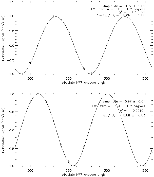
is given by A fit of the data (shown at right) to the 3 free parameters above
yields P = 97.0 and 97.3 %, δ = -36.8° and +30.4°,
and f = 0.86 and 0.88. The two sets of numbers are for tests
in which the calibration grid had the wires oriented vertically and
diagonally (45° CW from vertical looking towards the sky).
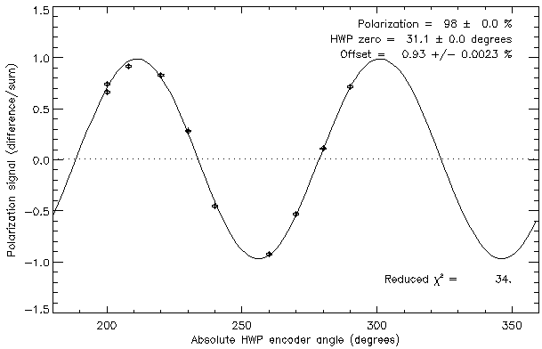
Set (3) resulted in a polarization efficiency of 98% with
negligible offset. The decrease in efficiency without the nylon sheet (set-up 2)
is most likely due to changes in detector loading. The data to the right is for the calibration grids with wires rotated 45° CW from vertical looking towards the sky).
V_null_encoder = 233.3°.
 .
.
where P is the polarization,
θ is the HWP angle, and f = Gv/Gh is
the ratio of the gains in the H and V arrays. (Note the error in the plot to the right. The legend reads "f = Gh/Gv" whereas the value given is actually "f = Gv/Gh"

The best estimate of δ with respect to vertical from the above data is -36.7° = 233.3°. Following the calculations from November we get
V_null_rel = 233.3 - 200 = 33.3°
HWP zero angle = 2 × 33.3 = 67°
Last updated by John Vaillancourt. 2006-Dec-14.
Return to SHARP analysis logbook.
Return to SHARP home page.