
| |
|||||||
|
The SHARP
polarimetry module |
||||
|
|
||||
|
Table
of Specifications |
||||||||||||||||||||||||||||||||||
|
a - all estimates of required flux for 450 micron band are +/- 20% b - assumes binning over 4 SHARP pixels, which is approximately one resolution element c - one SHARP pixel = 4.6 arcsec x 4.6 arcsec = 21 arcsec2
|
||||||||||||||||||||||||||||||||||
|
Optical Design |
||||
|
|
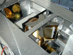
At left we show two views of SHARP. In the upper illustration, the submillimeter light beams from the Nasmyth focus of the CSO telescope enter SHARP from the left, and are relayed through an optical path including flat mirrors and curved mirrors as well as polarimetric components such as free-standing wire polarizing grids and a birefringent crystal. The light then passes into the M4 box (blue parallelogram at right of illustration) that contains the first mirror of the SHARC-II camera. The lower illustration shows the view looking at SHARP from the Nasmyth focus. The detailed photon path is as follows: First, an off-axis paraboloidal mirror collimates the expanding beam from the Nasmyth focus; then a gold-coated flat mirror directs the light toward the "crossed-grid" (see photo below) that serves to separate the incident radiation into two orthogonal polarization components. The two orthogonal components then travel in opposite directions as shown in lower illustration. (Just before it reaches the crossed-grid, the light is transmitted through a rotating birefringent crystal quartz half-wave plate that is not shown in these illustrations). After exiting the crossed-grid, there are more reflections by curved and flat mirrors, and then the beams come to a focus (see bottom of lower illustration) at the "beam combiner". The effect is to reconstitute the image but with an offset between the two polarization components. It is this divided image that is re-focused back into SHARC-II. The advantages of simultaneous detection of two orthogonal components of polarization are explained below.
|
|||
|
Dual
Polarization Capability |
||||
|
The photo at right shows the crossed-grid, a compact device that allows us to split polarization components without introducing long optical paths. This device, that was fabricated in the United Kingdom by TK Instruments, consists of two intersecting orthogonal free-standing wire grids. The "dual-polarization" capability not only avoids wasting photons, but more importantly serves to reduce noise. Specifically, we can reduce the effects of signal variations caused by variable atmospheric emissivity, called "sky noise". Sky noise is a very significant source of error, but it is correlated between polarization components, so dual-polarization capability allows us to remove it during data analysis. |
 |
|||
|
Modular Design |
||||
|
|
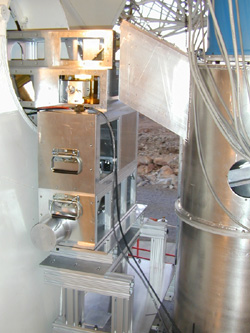
The photo at left shows the SHARP module installed at CSO. SHARP is the stack of four boxes, shaped like an inverted "L". The large cyllinder at right with parallelogram-shaped extension is SHARC-II. The light from the Nasmyth focus of the CSO telescope enters SHARP from the left. The top box can be removed to convert from polarimetry mode back to the ordinary SHARC-II camera mode. |
|||
|
Documentation for SHARP Observers |
||||
|
| ||||