1. Introduction
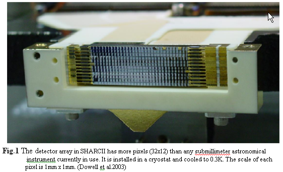
SHARC-II is a photometer which is used with the 10-meter CSO and can be operated at 350 or 450 µm. The basic idea is to build a module which can divide the incident beam into two orthogonally polarized components. The two components will then be sent to the opposite end of the 32 x 12 pixel bolometer array of SHARC-II (Fig.1). This module will turn SHARC-II into a dual-polarization polarimeter with the diffraction limited angular resolution ~ 8.
2. Optical design
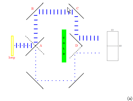
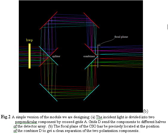
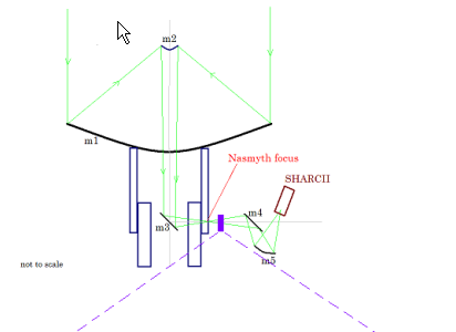
Fig.2(a) shows the simple version of the design. The crossed grids (A) divide the incident beam into two perpendicular polarization components (hereafter the crossed grids will be called the spliter). More reflections will send the components to opposite ends of the detector array. The last reflection is accomplished by another pair of grids D which will be called combiner hereafter. Behind the combiner is the cold load (<10K). The grid combiner and cold load will prevent the heat emission from the module itself reaching the detectors. To make sure that one component will only go to the correct half of the array, the Nasmyth focal plane of the CSO has to be precisely located at the combiner, Fig.2(b). Moreover, the module must keep the distance between focal plane and detector array unchanged. Two limitations of the CSO/SHARCII system cause this simple design to fail: (1) the space before Nasmyth focus is not accessible (Fig.3). (2) SHARCII is not movable so we can not compensate for the extra optical path length that the simple version of the design introduces (AB, BC, and CD in Fig.2(a)).
...............
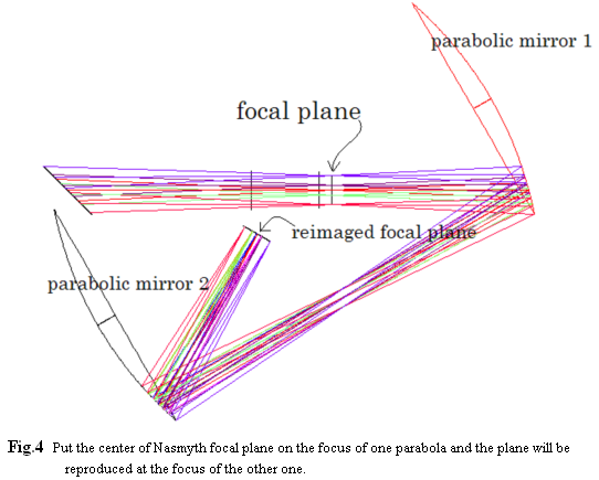
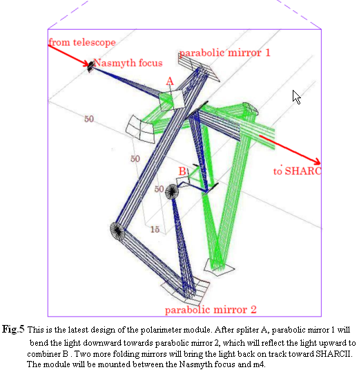
To solve these problems a two-parabolic-mirror reimaging system is introduced. Fig.4 is an illustration showing the principle of reimaging the CSO focal plane to another location. To make the module more compact, the reimaging optics and the basic optics are fused together as shown in Fig.5.
Note that in Fig.5, the distance from the Nasmyth focus to the 2nd folding mirror is the same as that between reimaged focus and that folding mirror. Thus, the whole module can be removed by just removing spliter A and the 2nd folding mirror. This makes it easy to switch between photometric and polarimetric modes of operation.
................
3. Performance simulation
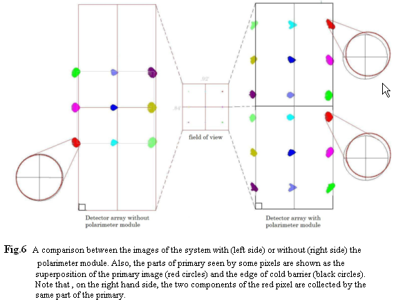
Next, I will show a ZEMAX simulation of the CSO/SHARC-II system with and without the module shown in Fig.6. ZEMAX is a program which can model and analyze the design of optical systems. First, light from 9 point sources distributed inside a 0.8*0.9 square arcmin field of view is sent towards the CSO. The result is shown in Fig.6 and we can see that basically the module works, all sources are clearly separated into two components. One thing should be noted is that inside SHARCII, in front of the array, there is a cold barrier which restricts each pixel to see exactly the primary. The red circle in the left hand side of Fig.6 shows this idea. The red circle stands for the image of primary on the surface of the cold barrier. The black circle is the edge of the barrier. You can barely see the black one because it exactly matches the red one (primary image). A negative feature of our polarimeter is that toward the edges of the field of view, the red and black circles no longer match each other (see the two red circles on the right hand side). This means that a pixel is not looking at the whole primary. We believe that the penalty will be small. However, we have to make sure the two polarization components are collected by the same part of the primary. Otherwise, this could cause a bias. We have adjusted the tilt angle of the combiner so that each corresponding pair of pixels uses the same part of the primary (Fig.6).
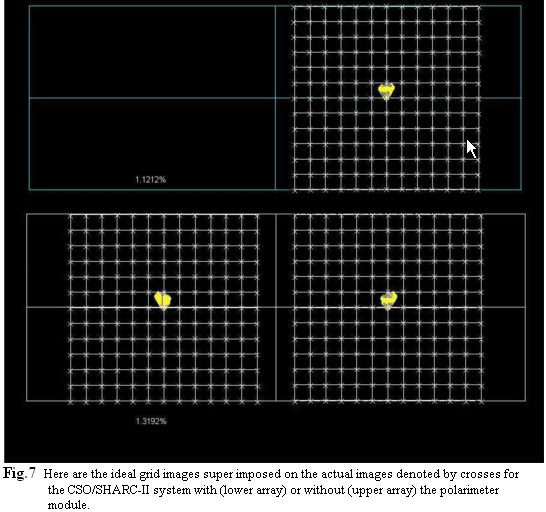
In Fig.7, we are study an array of point sources distributed like a grid. The image of each point source is marked with a cross. We should expect a grid-like image of crosses, if there is no distortion at all. The grid shown in Fig.7 are for reference only. They represent an ideal image. The actual image, will not be such a perfect grid, but is very close to it. The differences are only 1.1% without the polarimeter module and 1.3% with it. We can see that our module does not add any serious distortion to the CSO/ SHARC-II system.
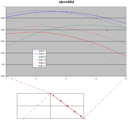
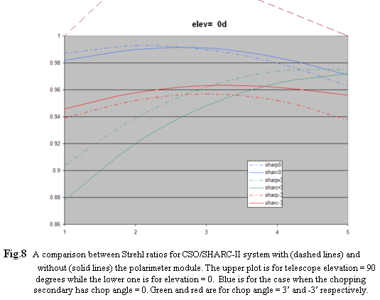
The last simulation I want to show is the Strehl ratio, which is a commonly used measure of optical image quality for very high quality imaging systems. We can see in Fig.6 that the images of point sources are not points. The Strehl ratio is the ratio between the peak intensities of two point spread functions. The first one is the actual point spread function and the second one is the ideal point spread function, called the diffraction point spread function. The closer we are to ideal performance, the closer to 1 is the Strehl ratio. In Fig.8, the various curves show Strehl ratios corresponding to different telescope elevations, different pixels, and different position of the chopping secondary mirror which works as a chopper. We can see that sometimes adding the module makes situation a little worse, but sometimes it is better, so on average, I think adding this module will not hurt the image quality of the original CSO/SHARC-II system.
....................
Hua-bai Li
h-li5@northwestern.edu
5/13/04