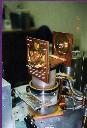
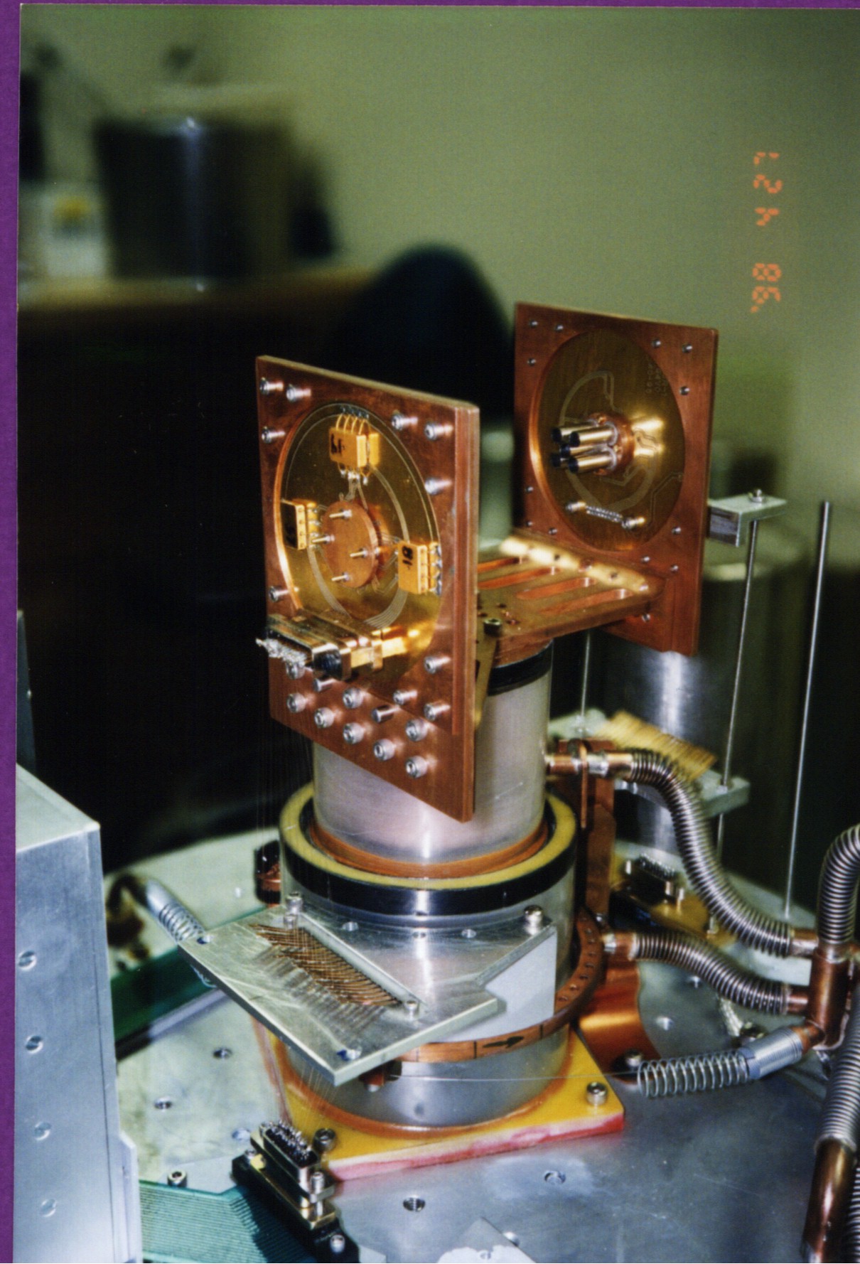
 small image & large image--SPARO in April 1998. Detectors installed, but no optics yet. Note SPARO is configured for 800 micron operation with 5 pixels only.
 small image & large image
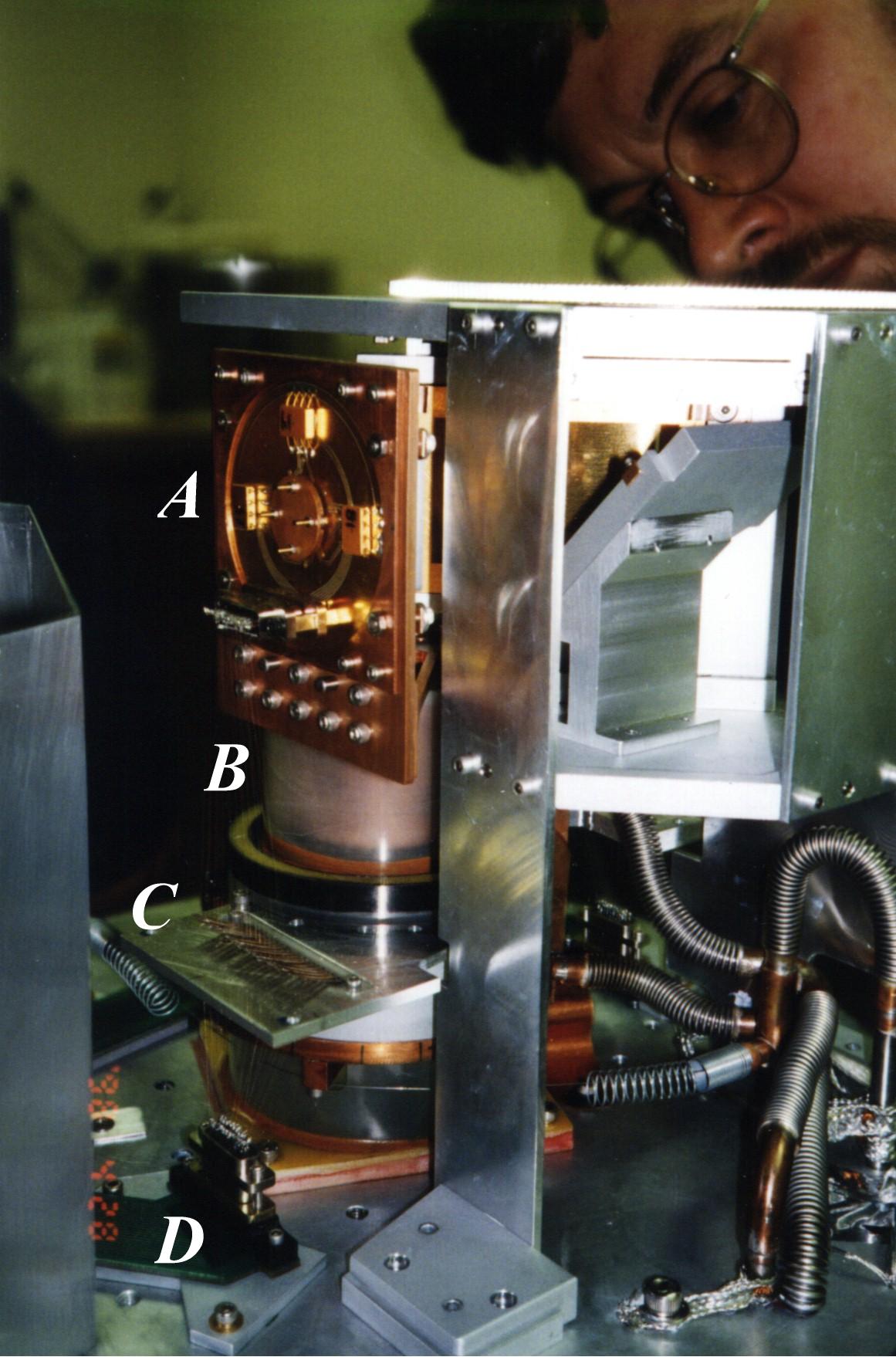
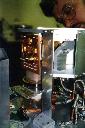
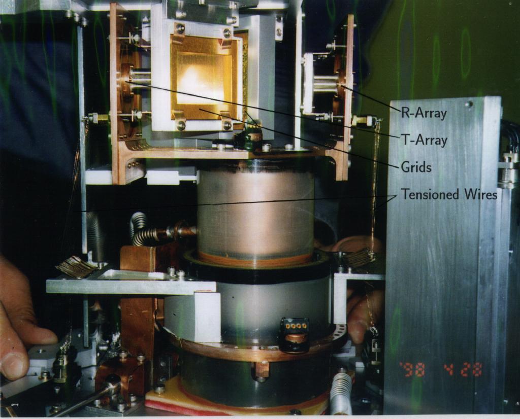
SPARO electronics (before installation of grid adjuster). This photo shows the signal path: back of detector array (A), the 2 mil diameter tensioned wires(B), leaf springs (C), and 4 K PC board (D).
 SPARO optics and electronics all installed. Photo taken at CSO in April 1998. Adjustable grid not yet installed. Lenses in front of detectors are no longer used.
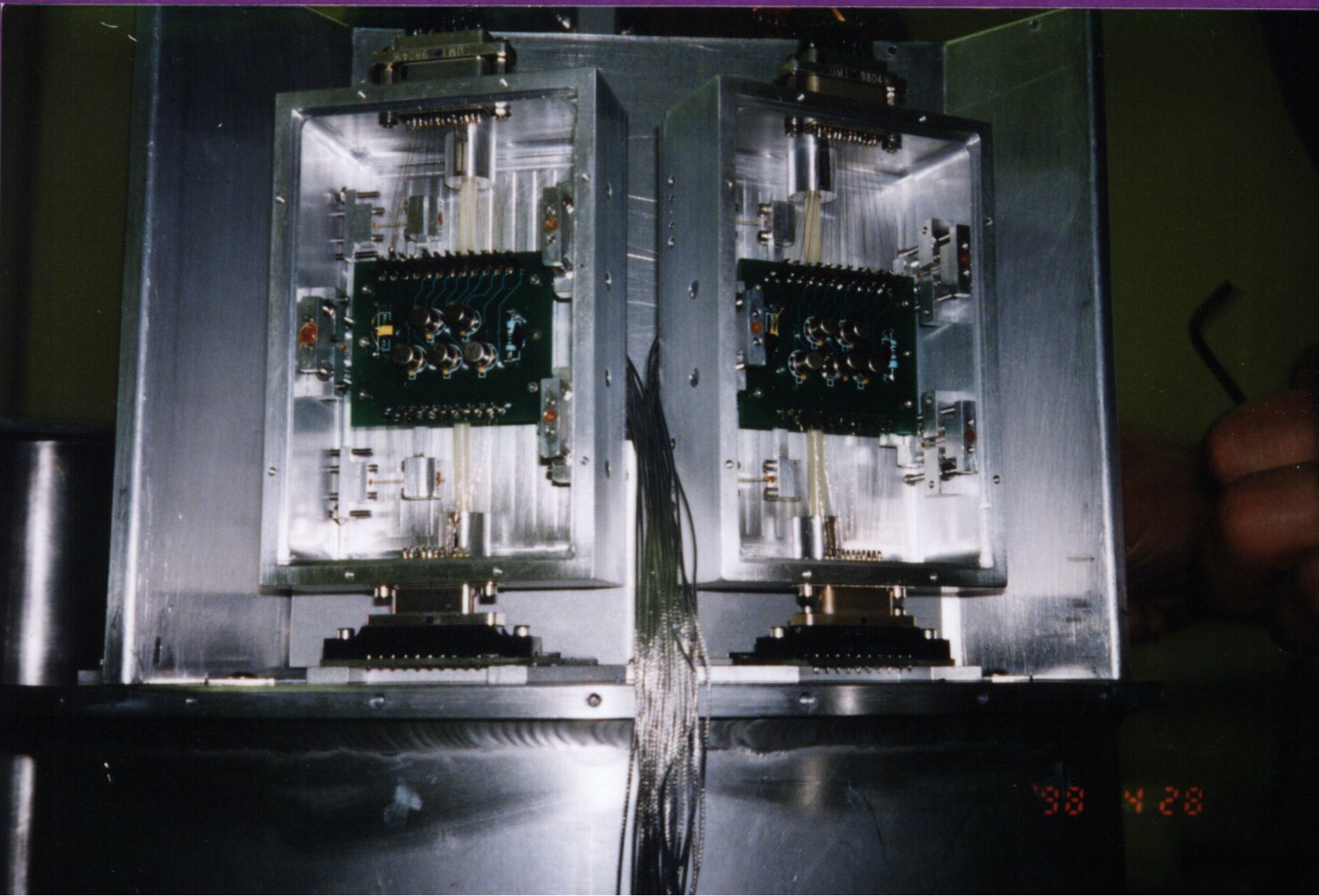
 small image & large image--JFET boxes are inside SPARO. Boards are heated to about 100 K. Here JFET boxes are shown with lids removed.
 small image & large image
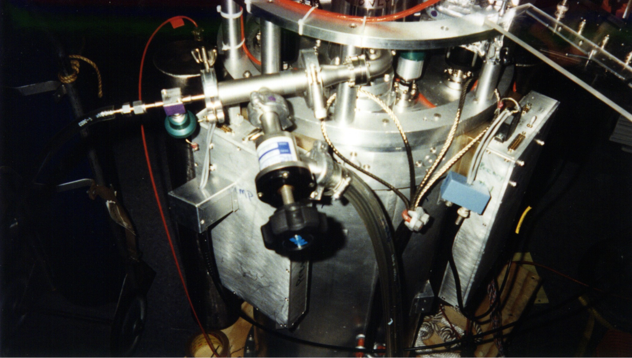
Photo of SPARO showing, primarily, the "pumped pot fixture," the fixture used for switching between pumping on the pumped pot and flushing the capillary with back-pressure. Green-handled valve is used to connect pumped pot to UHP Helium gas; black-handled valve is used to connect pumped pot to mechanical pump. Photo also shows the large preamp boxes on either side, attached to which are the small laboratory JFET breakout boxes (one is aluminum, the other is painted blue).
 small image & large image--Preamp and data system power cables for running SPARO in lab.
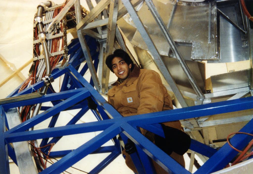 Prashant Malhotra strings SPARO cables through cable wrap--Pole 1998.
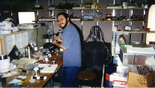 Tom Renbarger prepares for final tests of the SPARO preamps.
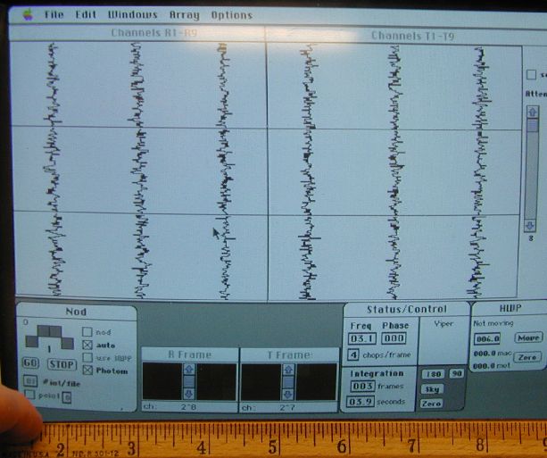 Photo of screen of Macintosh data system computer.