Below are information and recommendations made by Martin, Mark, and Giles, after they studied Paolo's report of May 20:


Mark Thoma has explained that the current from the mirror heater system power supply to the mirror heater system chassis flows down a single AWG 4 cable. (with another such cable for the return.) This multi-strand cable is separated into two bundles of conductors before being connected to the mirror heater system chassis. Mark Thoma also explains that this cable is rated to carry 100 Amps and should *not* be too hot too touch with 70-80 Amps. At this current, it should be only slightly warm to the touch. Mark believes that there is probably a bad connection somewhere. Mark suggests that the connections should be inspected, and possibly repaired. Specifically, in the photo below, the part of the system that is within the red oval is the part that Mark thinks might be damaged. He thinks that the heat or some other factor may have damaged one or more of the four crimp-on lugs that are on the ends of the awg 4 cable. These should be inspected for discoloration (oxide layer) or loose-ness. The heat could cause an expansion that can make the crimp-on lug become loose. Mark has seen this happen before. If they are discolored or loose then they should be replaced or re-connected. There should be more crimp-on lugs in the Viper control room or pump room. There should be a crimp tool in the tool box. Alternatively, these connectors can be soldered to the cable. This will work fine. Giles suggests that the screws on the back of the *main heater system chassis* should also be inspected in case they too are loose. 
 
Fig. 4
 
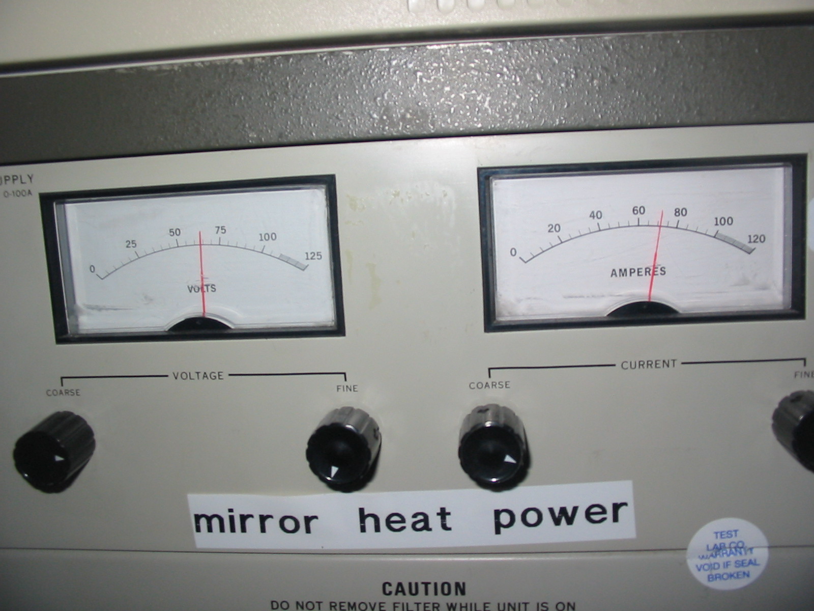
Note that in the photo below you can see that the mirror heater system power supply has an adjustable current limit (two knobs - "fine" and "coarse"). Mark Thoma says that Giles' suggestion of reducing the current limit to 40-50 Amps is not unreasonable. There are 8 channels drawing 10-12 Amps or less per channel, so that explains why the "full heat on" level is at 70-80 Amps.
 
Fig. 1
 
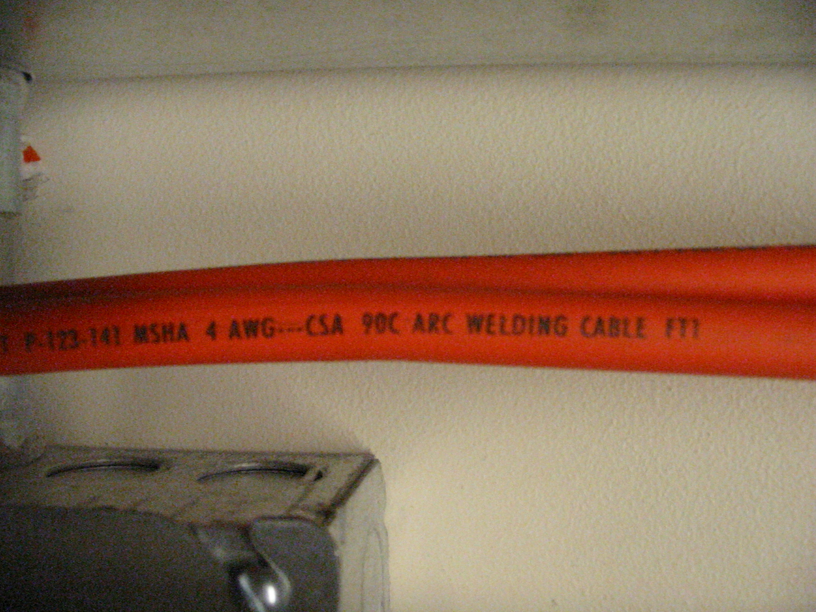
Paolo writes: "The cable is an AWG 4, with two conductors for each polarity." However, as Mark explains, there is only *one* conductor for each polarity.
 
Fig.
 
Paolo writes: "I esteemed [estimate] about 105-110 F (40-45 C) in this conditions. However, as you can see the cable is safe till 194 F (90 C)." According to Mark, the cable should be safe to 200 C. He thinks that perhaps the "90C" that is printed on the cable does not refer to temperature, but is some other sort of specification.


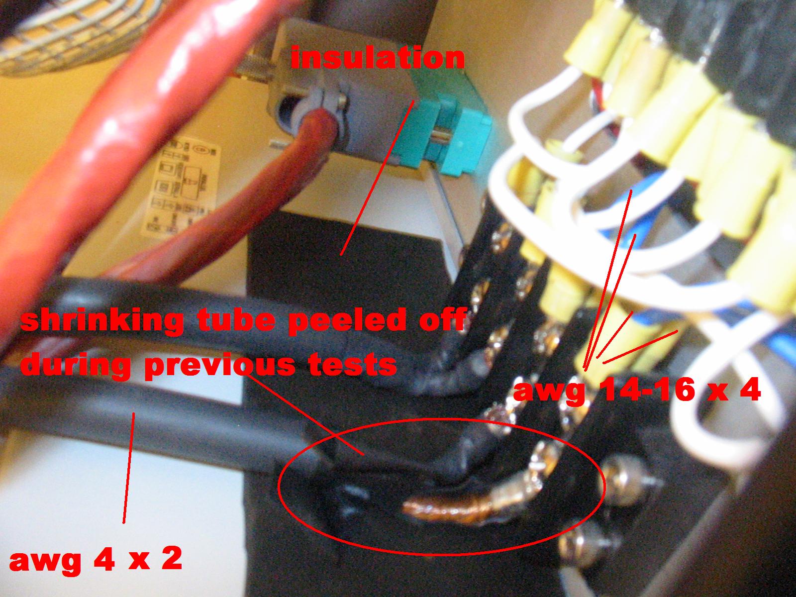
Paolo writes: "It is puzzling why the cyan and white cables, probably awg 14-16 or close (I can't really tell), visible in next pictures are not overheat much worst." Mark explains that these are awg 12 wires, rated for about 25 Amps, and that each wire carries the current for only 1-2 channels. Because the maximum current per channel is 10-12 Amps, these wires never carry more current than they are rated for. That is why they do not overheat. Mark thinks that the reason that the AWG 4 cable *does* get hot is because of a bad connection, as explained above.
 
1) "Martin" heater PC shutdown
The leds situation is as follows:
Fig. 5
Paolo writes: "As soon as the heater PC is switched off (and not before) the system get apparently completely out of control. not corresponding to the normal condition as all the green lights slowly switch off, while in standard conditions only a few of them switch off and on time by time." Martin points out that the control of the main heater system is completely analog. I.e., the control is by the main heater system electronics chassis. Thus it seems very unlikely that turning the computer off should have any effect on the operation of the main heater system electronics chassis. So none of us here in US can understand how it is possible that the green lights should slowly turn off following a computer power-down. We suggest that Paolo should repeat this experiment and pay close attention to the result. Probably the green lights will start to come on again if you leave the computer off for long enough. Paolo further writes: "This means in my humble opinion that the electronics is still measuring the correct temperatures and that seea the various subsystem overheating." This statement is confusing because it is the mirror heating system that is overheating and the main heating system chassis should be operating normally and under analog control with the computer on, and should continue to operate normally and under analog control when the computer is turned off. The overheating of the mirrors should not cause the main heater system to react, as the main heating system is completely separate from the mirror heating system.
...
One last point - Martin thinks that he understands why the mirror system goes into full-on mode when the computer is powered down. Basically, there is a pull-up circuit that pulls the output up to 5 V (=OFF) when there is "no activity". But when the computer is turned off this pull-up does not work as there is no more 5 V reference. This seems to be a "feature" of Martin's system that we have to live with.
...
Paolo: I hope this is helpful in some way. Please send e-mail or call me to clear up any confusing points in this document.
 
- Giles