 larger
|
larger |
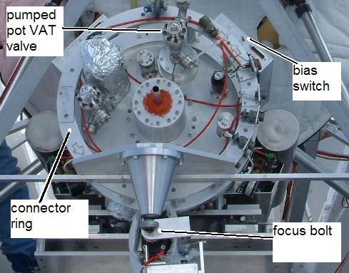
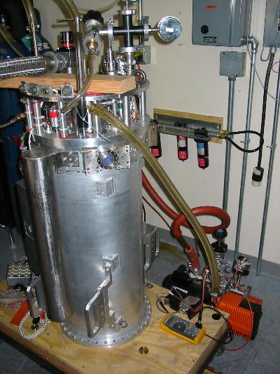
Fig 1 - SPARO on Viper (2003) - showing bias switch on one of the preamps, the connector ring, the focus bolt, and the pumped pot vacuum valve. |
 larger larger |
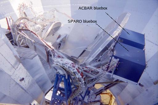
Fig 2 - SPARO blue box and ACBAR blue box (2001). |
 larger larger |
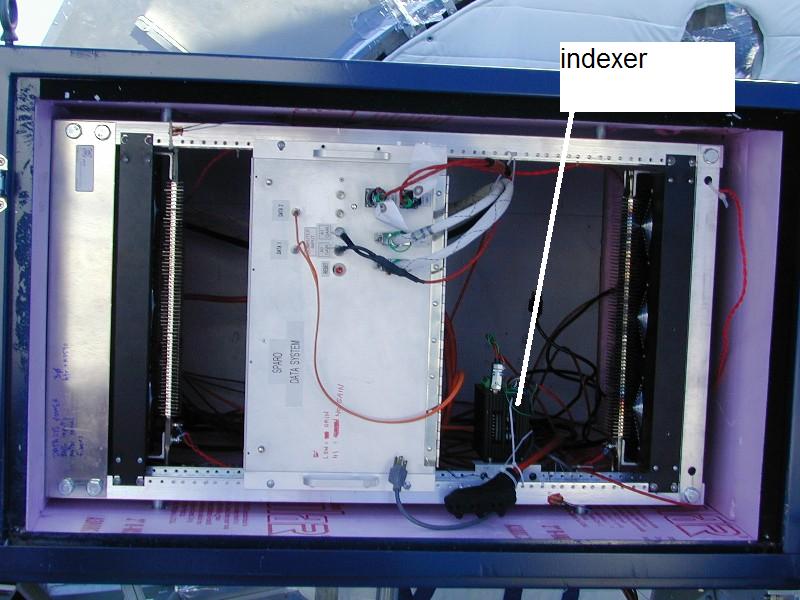
Fig 3 - inside of SPARO blue box (2001), showing indexer. |
 larger larger |
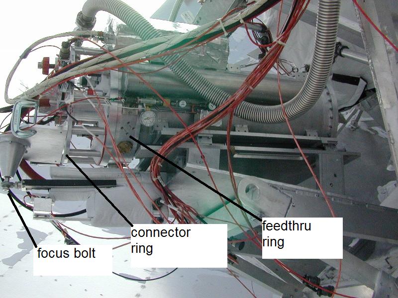
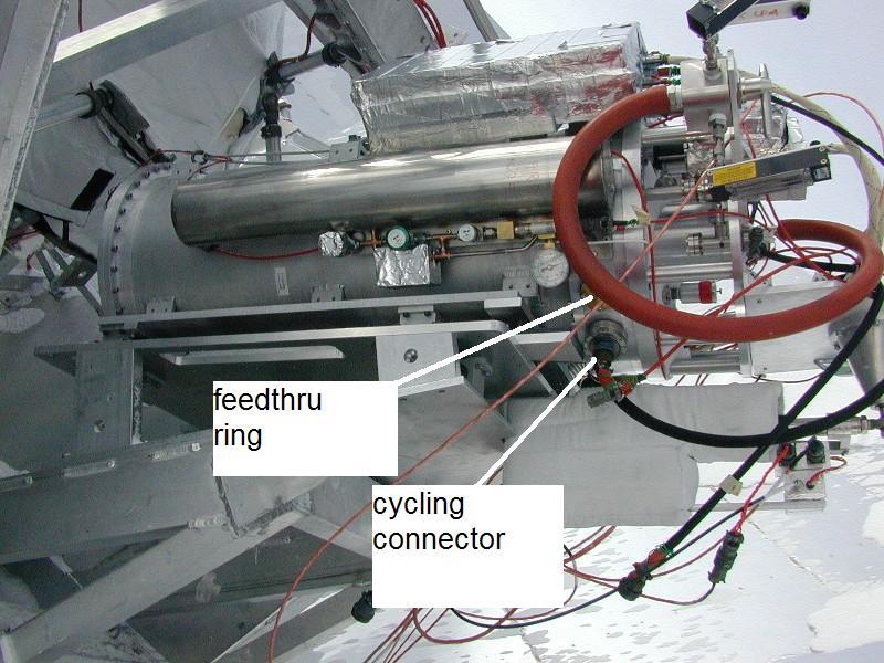
Fig 4 - SPARO on Viper (2001), showing focus bolt, connector ring, and feedthru ring. |
 larger larger |
Fig 5 - SPARO on Viper (2001), showing cycling connector that plugs into a feedthru on SPARO's feedthru ring. |
 larger larger |
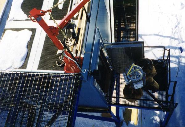
Fig 6 - Overhead crane used to install and remove SPARO (2003) |
 larger larger |
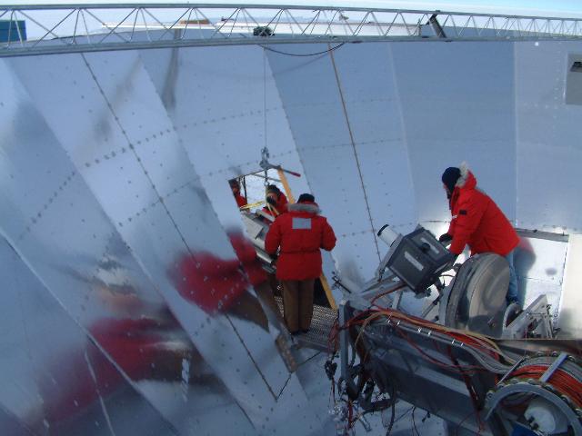
Fig 7 - SPARO being installed to Viper (2003) |
 larger larger |
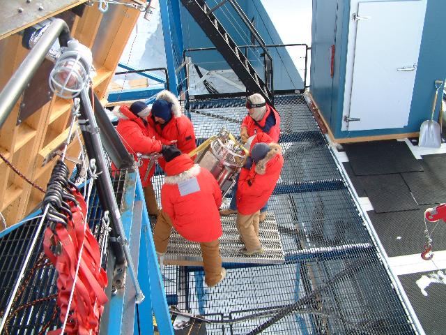
Fig 8 - SPARO on the hoist (2001) |
 larger larger |
Fig 9 - SPARO on its cart (2003) |
 larger larger |
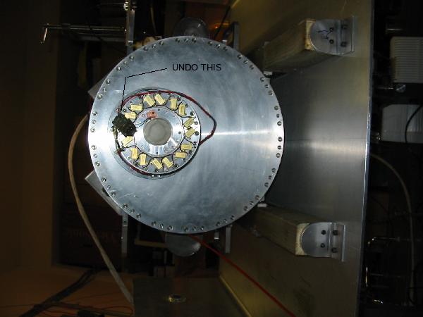
Fig 10 - Undo and secure this connector before putting SPARO on cart (2003) |
 larger larger |
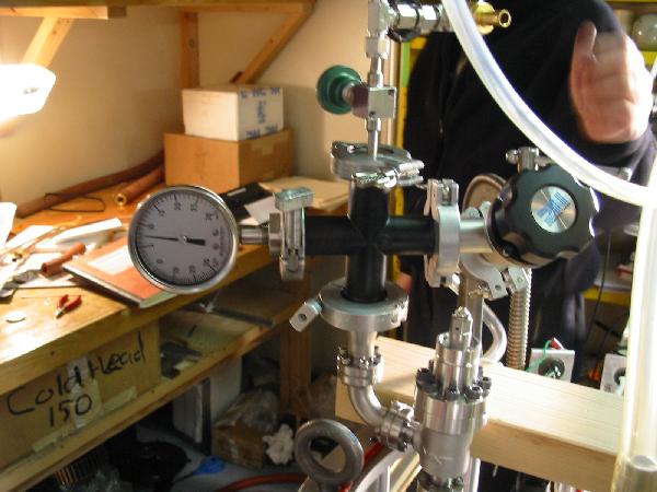
Fig 11 - A view of the "flushing fixture" that attaches to SPARO pumped pot port (2003 photo). |
 larger larger |
Fig 12 - Another view of this "flushing fixture". The use of this fixture allows one to either pump on the pumped pot, or apply back pressure as is typically used for warmup and cooldown. (2003 photo). |
 larger larger |
Fig 13 - Diagram of the flushing fixture and the reservoir pumping fixture. (Reservoir pumping fixture used for cooldown only.) |
 larger larger |
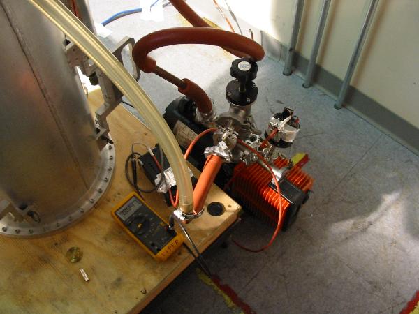
Fig 14 - Mechanical pump used to pump on pumped pot, with capacitance manometer gage (2003) |