- Step 1: Remove the Outer Case
- Step 2: Remove the OVCS
- Step 3: Remove the IVCS
- Step 4: Install "L" Brackets
- Step 5: Remove the 4 K Shield Lid
- Step 6: Remove the JFET Shield Lid
- Step 7: Remove the 4 K Shield
- Other steps:
- Breaking Indium Seals
Step 1: Remove the Outer Case
- Install the neck-tube support rod. This is a long stainless-steel solid rod that just fits within the neck-tube. It drops all the way to the bottom of the reservoir. One end of this rod is slightly tapered. Tape this support rod to the neck-tube where it sticks out, using aluminum tape.
- Once the neck-tube support is installed then the dewar will next need to be inverted. It will have to rest on the "ring" (with the fill-tube poking through the hole in the cart). So all attachments need to be removed from the ring. This includes the L-bracket connectors for heaters/motor, and the focus attachment. Before inverting the dewar, check that nothing sticks up so far as to hit the floor when inverted.
- Invert the dewar. It is heavy and can be a four person job, and takes some planning to execute smoothly. It may help to lighten the dewar by removing things like the big rectangular mounting frame with little feet (that serves to mount to Viper).
- Break the indium seal to the case lid and remove it from SPARO (with snout attached). (See special notes on breaking indium seals at end of these instructions.)
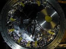
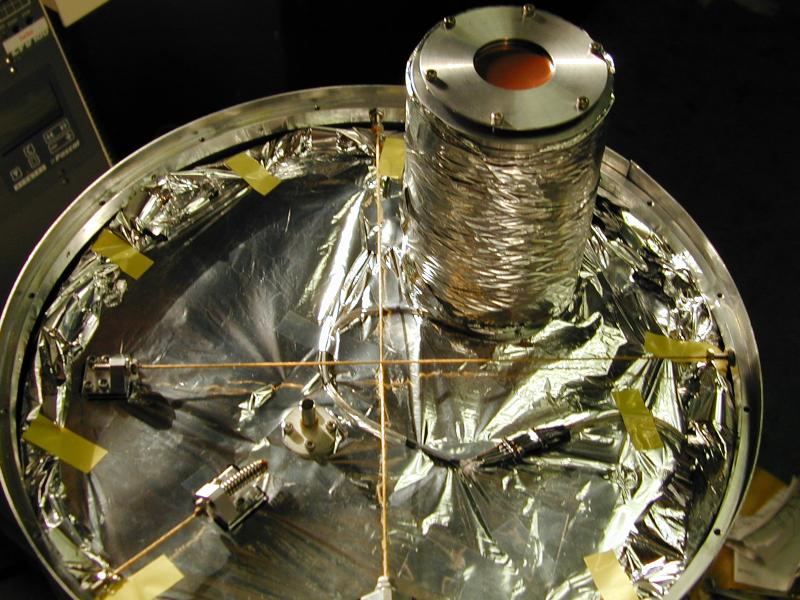
- You will see three Kevlar
supports that run from the OVCS lid to the inside of the
outer case (see Figures 1 and 2). One of these Kevlar lines has a
spring. The
other two are "fixed". To aid in reassembly, you may want to mark
the positions of the three "feet" that attach to the OVCS lid by
tracing their positions with a marker. This will save time later,
since some of them fit best when displaced from their 4 hole footprint.
Compress the spring slightly to
relieve the tension on the fixed supports. While one person
compresses this spring, another person should
remove the
screws that hold the two fixed Kevlar supports to the OVCS case
lid. Drape
these two Kevlar lines over the outside of the outer case
to get them out of the way. Next remove the final Kevlar
support (the one with the spring) by loosening the screws that hold it to
the OVCS
lid. Drape it over the outside of the outer case as
well.
 larger
Fig 1- view of OVCS lid after case lid removal, showing three Kevlar supports: two fixed, one with spring. 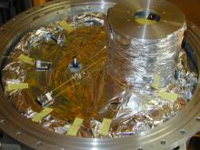 larger
Fig 2- another view of same. - Break the indium seal between the assembly ring and
the outer case. (Again, see notes below.) Carefully lift the
outer case off. Remove the MLI(mylar insulation) and store in a safe
place.
This superinsulation blanket is composed of 10 sheets taped together with mylar
tape and then wrapped around the OVCS in one piece. It should be able to
be taken off as one piece. This will make it much easier to put it back on.
NOTE: ONCE THE OUTER CASE IS REMOVED, THE DEWAR IS IN A FRAGILE STATE
UNTIL THE "L" BRACKETS ARE INSTALLED. THE ONLY SUPPORT AGAINST
LATERAL MOVEMENTS DURING THIS PHASE IS THE NECK TUBE. BE
CAREFUL NOT TO UNNECESSARILY JOSTLE THE DEWAR.
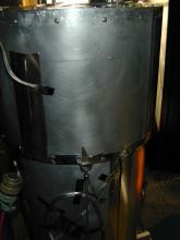
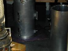 larger
Fig 3- outer case of SPARO. Note it is set down on something soft so as to avoid ruining the seals.
 larger
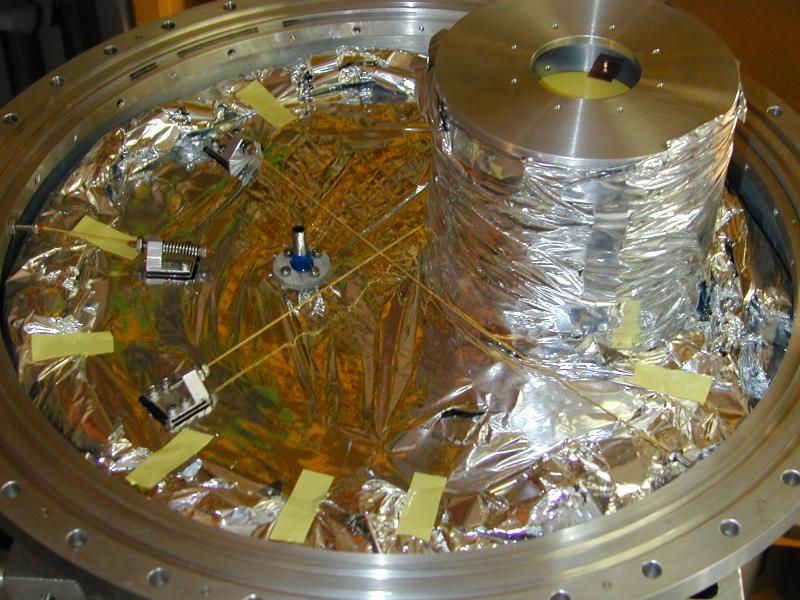 larger
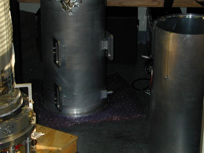 larger
Step 2: Remove the OVCS
- remove the aluminum tape from the top and bottom seams of
the OVCS.
 larger
Fig 4- tape on top seam.  larger
Fig 5- tape on bottom seam. - remove the OVCS lid (with snout attached)
To do this, remove the allen bolts on the top (see Fig. 6).
The pan head screws on the side of the OVCS simply
hold the rolled aluminum shell to a support ring.
 larger
Fig 6- Remove these only. - You will see three more kevlar supports. Remove these exactly as you did before (step 1 above). Again, you should mark the position of the feet before removing them. Drape them over the outside of the OVCS.
- Remove the bottom row of 4-40x1/4 phillips head screws that attach the OVCS to
the bottom OVCS lid (see Fig. 7). (The top row hold the OVCS
rolled aluminum
shell to a support ring)
 larger
Fig 7- Bottom screws. Only remove the bottom row. - Carefully lift the OVCS up and off. Use your thumbs to push down on the IVCS if needed to loosen this sticky OVCS.
- remove the MLI.
 larger
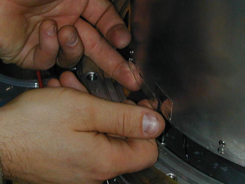 larger
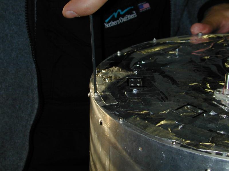 larger
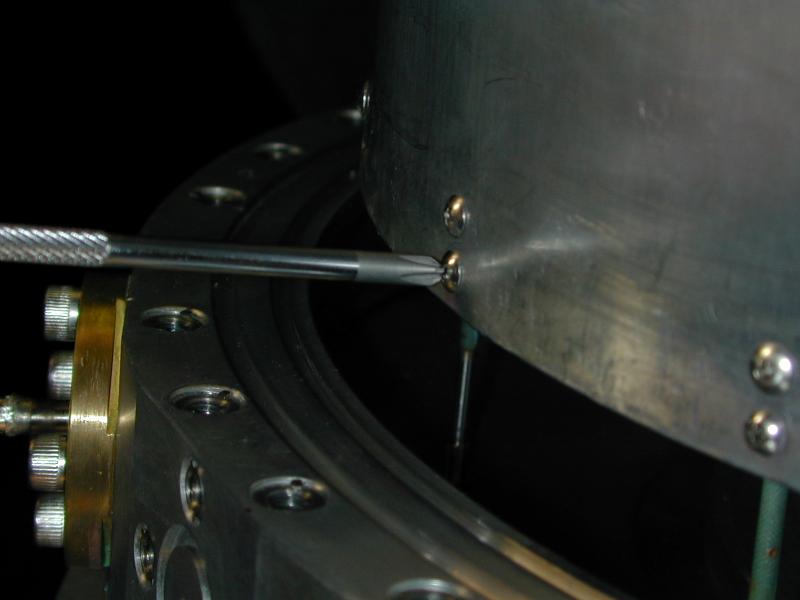 larger
Step 3: Remove the IVCS
-
Repeat step 2 but for the IVCS. CAUTION:
THE ONLY
LATERAL SUPPORT COMES FROM THE NECK TUBE. BE CAREFUL NOT TO
UNNECESSARILY JOSTLE THE DEWAR.
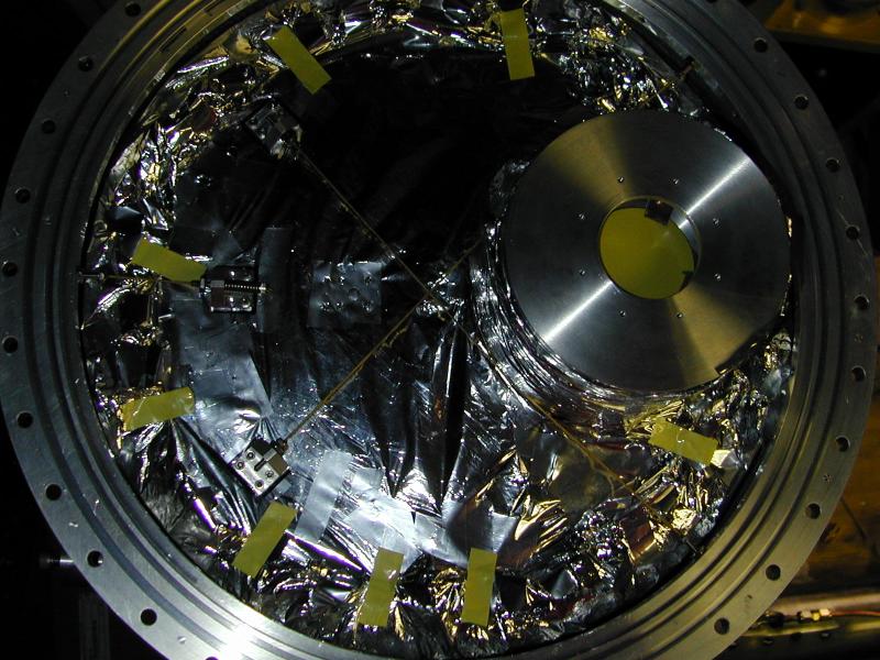
 larger larger |
Fig 8- This shows a view of the lid of the 4K shield that you will see after removing the IVCS lid. |
Step 4: Install "L" Brackets
-
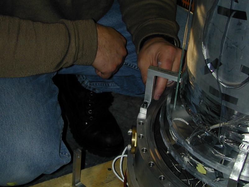
Apply the four "L" brackets which connect the He-4 reservoir to the
accessory ring. These are shown in Fig. 9 and Fig. 10. These attach via
1/4-20 bolts to the accessory ring and
extend inwards attaching
to the underside of the Helium reservoir. The threaded holes can be
hard to find, but you should be able to feel them without removing the
superinsulation which is taped to the bottom of the 4K reservoir. To tighten
these bolts, you need a special
"sawed off" allen wrench, though this may be accomplished with a pair
of pliers.
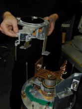
 larger larger |
Fig 9- The L-brackets |
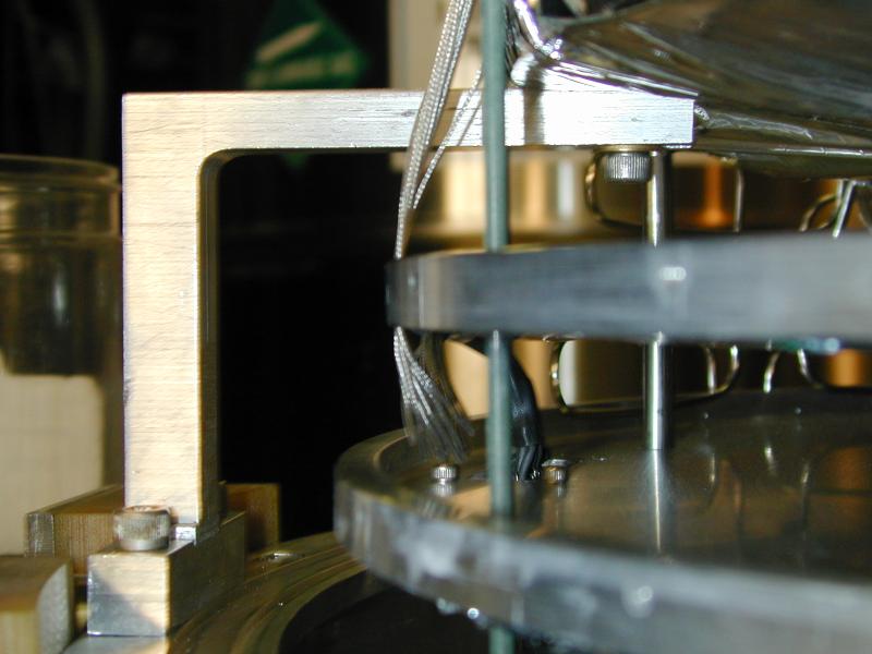 larger larger |
Fig 10- Another view of the L-brackets |
Step 5: Remove the 4 K Shield Lid
- This will be the hardest step in the process, so far. The reason it is hard is that the set screw that you would ordinarily want to loosen cannot be removed because we accidentally ruined the Allen socket in the set screw during the disassembly in 2001. But with care, it should be possible to remove the 4 K shield, as follows:
- First note that the 4 K shield lid contans the smallest nested snout of the SPARO cryostat. This snout houses the field lens and the half wave plate module (HWP).
- Remove the tape from the seams of the 4 K shield lid.
- Remove the precut black foam piece on the hwp shaft where it enters the cold plate.
- Ordinarily, you would next loosen the coupler to the HWP shaft by loosening the set screw(0.035 Allen wrench) that bites into the flat part of the shaft (see Fig. 11). But this set screw cannot be removed, unfortunately. So you will instead proceed with the following alternative disassembly steps:
- Before proceeding, note that there is an electrical connection that needs to be undone (the hwp encoder). Note the polarity so you can later reattach it.
- You should have enough play to unbolt the 4 K shield lid (with
snout attached) and raise it about 1 cm. You cannot raise it further
because to the hwp shaft is connected. But you should be able to
carefully
rotate this lid about the shaft, until you can gain access to
inside the 4 K shield. Then you can carefully undo the set
screw of the hwp coupler that is inside the 4 K shield (see Fig.
12). This will allow you to fully detach the lid of the 4 K shield.
This is a tricky job because your Allen wrench will be within a
cm of the very delicate tensioned wires that carry the signals. But with
enough patience and
courage, anything is possible.
 larger
Fig 11- In this image you can see the shaft coupler that cannot be removed because we accidentally ruined the socket in 2001. (it is shown with an Allen wrench sticking out of it.) 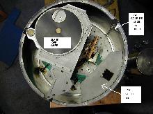 larger
Fig 12- this is the coupler that you need to undo instead of the one shown in fig. 11.
 larger
 larger
Step 6: Remove the JFET Shield Lid
-
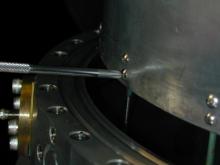
Fig 12 shows the lid of the JFET radiation shield. This needs to be
removed next. There are about four tiny screws that bolt sideways into
the lid, passing through the thin side-walls of the radiation shield.
Again, care is required as your Allen wrench will be very close to
the tensioned wires that carry the signals. (The fat bolt on top
merely serves as a handle - don't undo it.)
Step 7: Remove the 4 Kelvin Shield
- This step is similar to what you did for the OVCS and IVCS shield
removal.
 larger
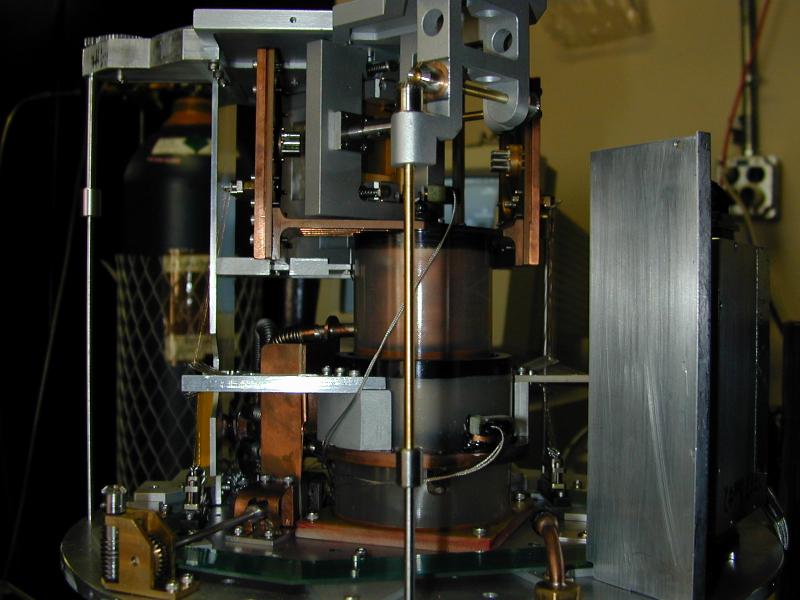
Fig 13- View of what is inside the 4 K shield. Grid adjustment shaft at center, blank-off wheel shaft at left, side wall of JFET radiation shield at right. 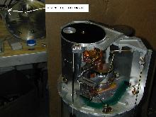 larger
Fig 14- View of what is inside the 4 K shield. In the background is the 4 K shield lid with hwp module. An arrow points to the bushing that galled in winter 2000, causing hwp failure. It was rebuilt in winter 2000. 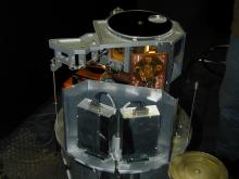 larger
Fig 15- View of what is inside the 4 K shield, with good view of JFET boxes.
 larger
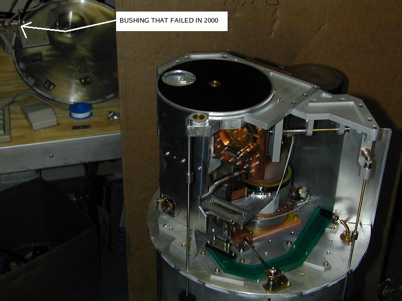 larger
 larger
Other steps that may or may not be needed.
- If necessary, it is easy to remove the JFET radiation shield. (see assembly instructions and work backwards.)
- The optics module can be removed (fig. 16) but unfortunately once
again we have a ruined shaft coupler socket that would have to be dealt
with.
 larger
Fig 16- Optics module was removed at Pole in January 2001  larger
Fig 17- View of SPARO insides with optics module removed. 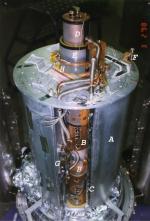 larger
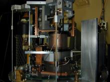
Fig 18- 1997 photo during construction. A: He-4 reservoir; B: He-3 charcoal pumps; C: pumping line for "pumped pot"; D: inner He-3 pot; E: outer He-3 pot; F: heat switch for He-3 pots; G: heat switch for charcoal pumps; H: capillary from main reservoir to "pumped pot"
 larger
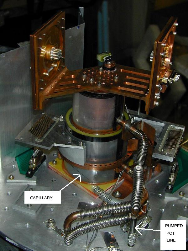 larger
 larger
Breaking Indium Seals
Indium is toxic. So wash your hands afterwards. Alternatively, use the latex gloves stored near the indium. Put waste indium into the indiium recycling bag.- Remove all the bolts used to make the seal and store these and the associated springy washers in the plastic boxes provided.
- Use "pry screws" to break indium seals. Pry screws are special screws that have very flat (machined) ends so that they can be threaded through one of the two mating pieces and then contact directly onto the other of the two mating pieces. As you tighten these screws down, the mating pieces come apart. Use many of these screws and tighten sequentially to gradually and gently pry the mating surfaces apart. Special holes have been provided for the pry screws.
- pull out the indium and store in the recycling bag.
- use sharp pointy tool stored near indium to get all of it out and safely stored away in the bag