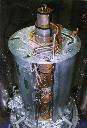
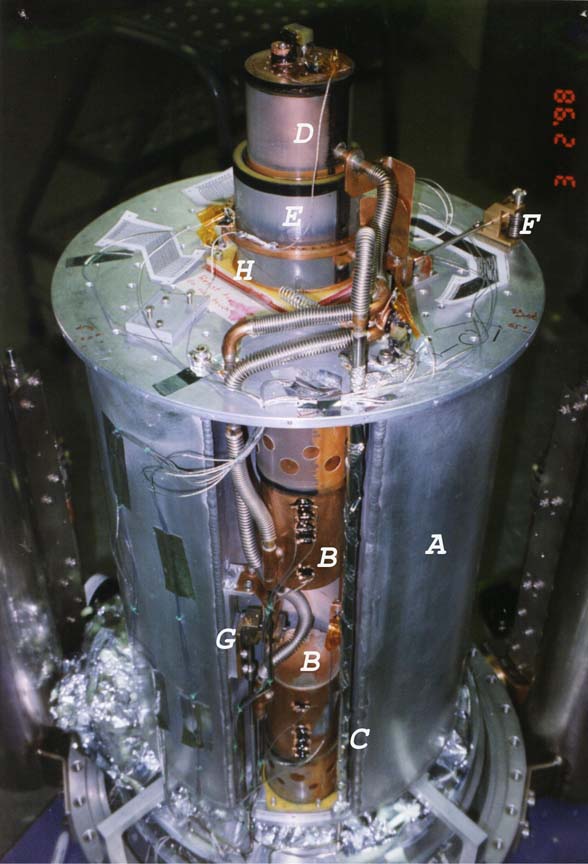
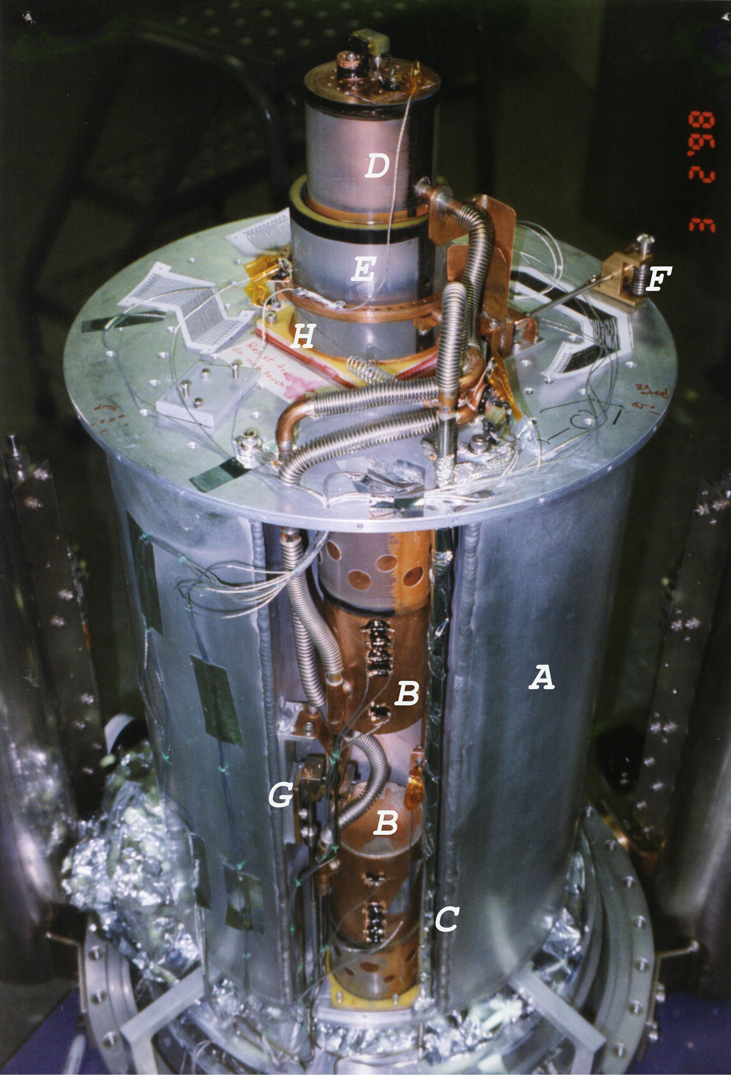
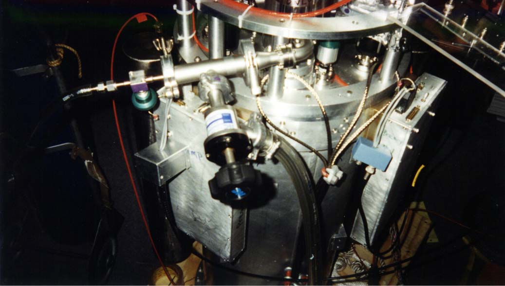
 small image & large image--SPARO cryostat in March 1998 before installation of detectors and optics. This picture shows the 4He reservoir (A), 3He charcoal punmps for inner (detector) and outer (guard) 3He stages (B), pumping line for 1.5 K pumped pot (C), inner stage 3He pot (D), outer stage 3He pot (E), part of the heatswitch for 3He pots (F), heat switch for charcoal pumps (G), and 0.005" i.d. capillary tube connecting 1.5 K pumped pot to 4 K 4He reservoir (H). small image & large image--SPARO cryostat in March 1998 before installation of detectors and optics. This picture shows the 4He reservoir (A), 3He charcoal punmps for inner (detector) and outer (guard) 3He stages (B), pumping line for 1.5 K pumped pot (C), inner stage 3He pot (D), outer stage 3He pot (E), part of the heatswitch for 3He pots (F), heat switch for charcoal pumps (G), and 0.005" i.d. capillary tube connecting 1.5 K pumped pot to 4 K 4He reservoir (H).
|
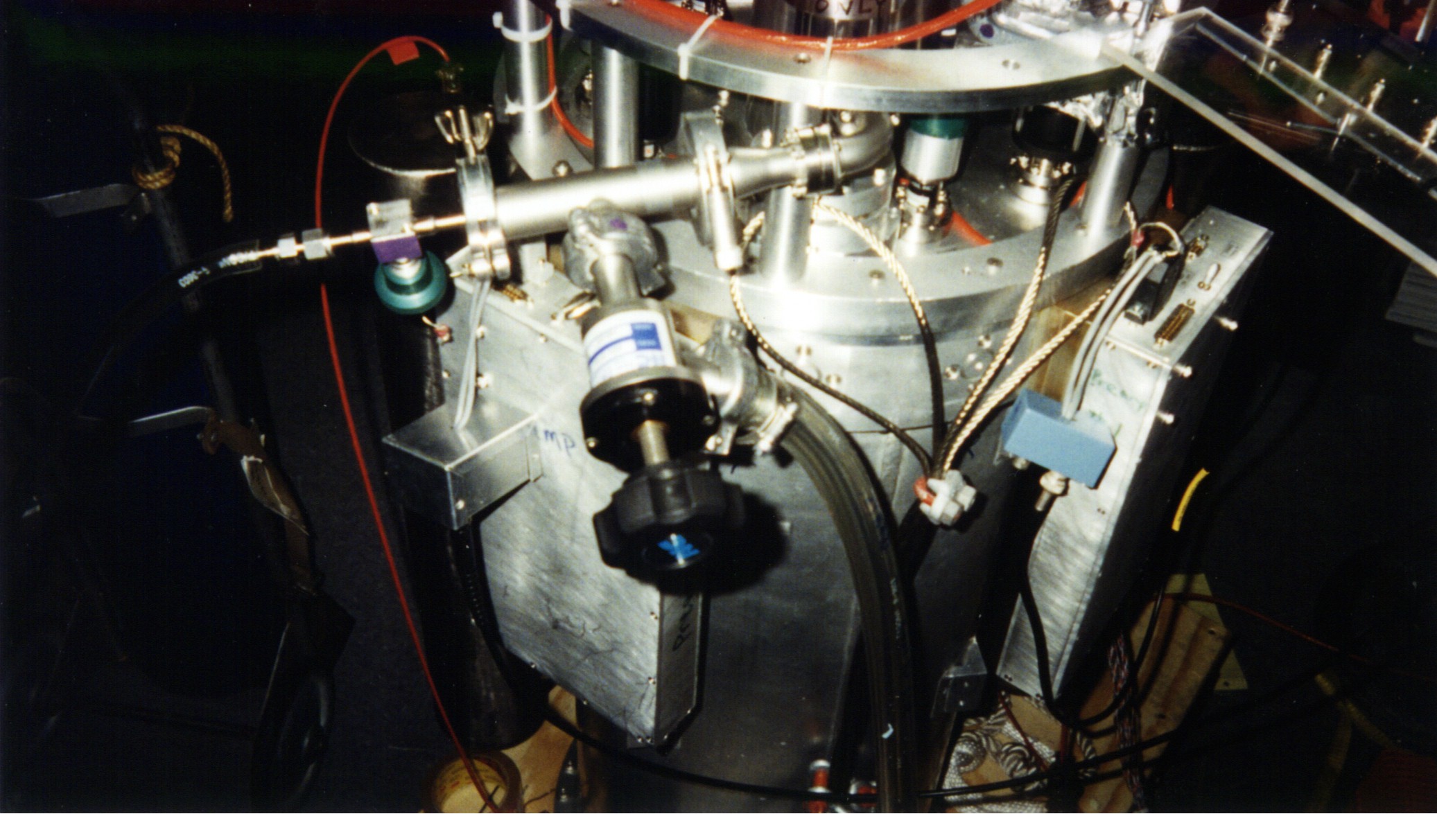
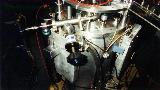 small image & large image--Photo of SPARO showing, primarily, the "pumped pot fixture," the fixture used for switching between pumping on the pumped pot and flushing the capillary with back-pressure. Green-handled valve is used to connect pumped pot to UHP Helium gas; black-handled valve is used to connect pumped pot to mechanical pump. Photo also shows the large preamp boxes on either side, attached to which are the small laboratory JFET breakout boxes (one is aluminum, the other is painted blue). small image & large image--Photo of SPARO showing, primarily, the "pumped pot fixture," the fixture used for switching between pumping on the pumped pot and flushing the capillary with back-pressure. Green-handled valve is used to connect pumped pot to UHP Helium gas; black-handled valve is used to connect pumped pot to mechanical pump. Photo also shows the large preamp boxes on either side, attached to which are the small laboratory JFET breakout boxes (one is aluminum, the other is painted blue).
|
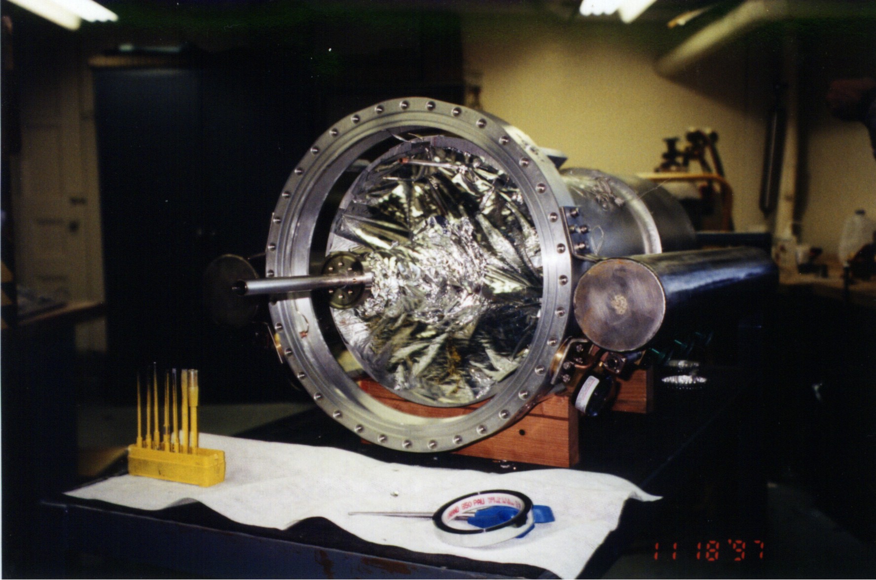
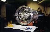 small image & large image--SPARO after removal of fill-tube case endplate small image & large image--SPARO after removal of fill-tube case endplate
|
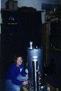 small image & large image--Jill Hanna assembles SPARO at Pole in 1998. One of vapor-cooled shields is visible. small image & large image--Jill Hanna assembles SPARO at Pole in 1998. One of vapor-cooled shields is visible.
|
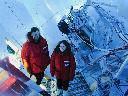 SPARO installed on Viper (February 2000), pictured with Giles Novak and Jen Marshall. SPARO installed on Viper (February 2000), pictured with Giles Novak and Jen Marshall.
|
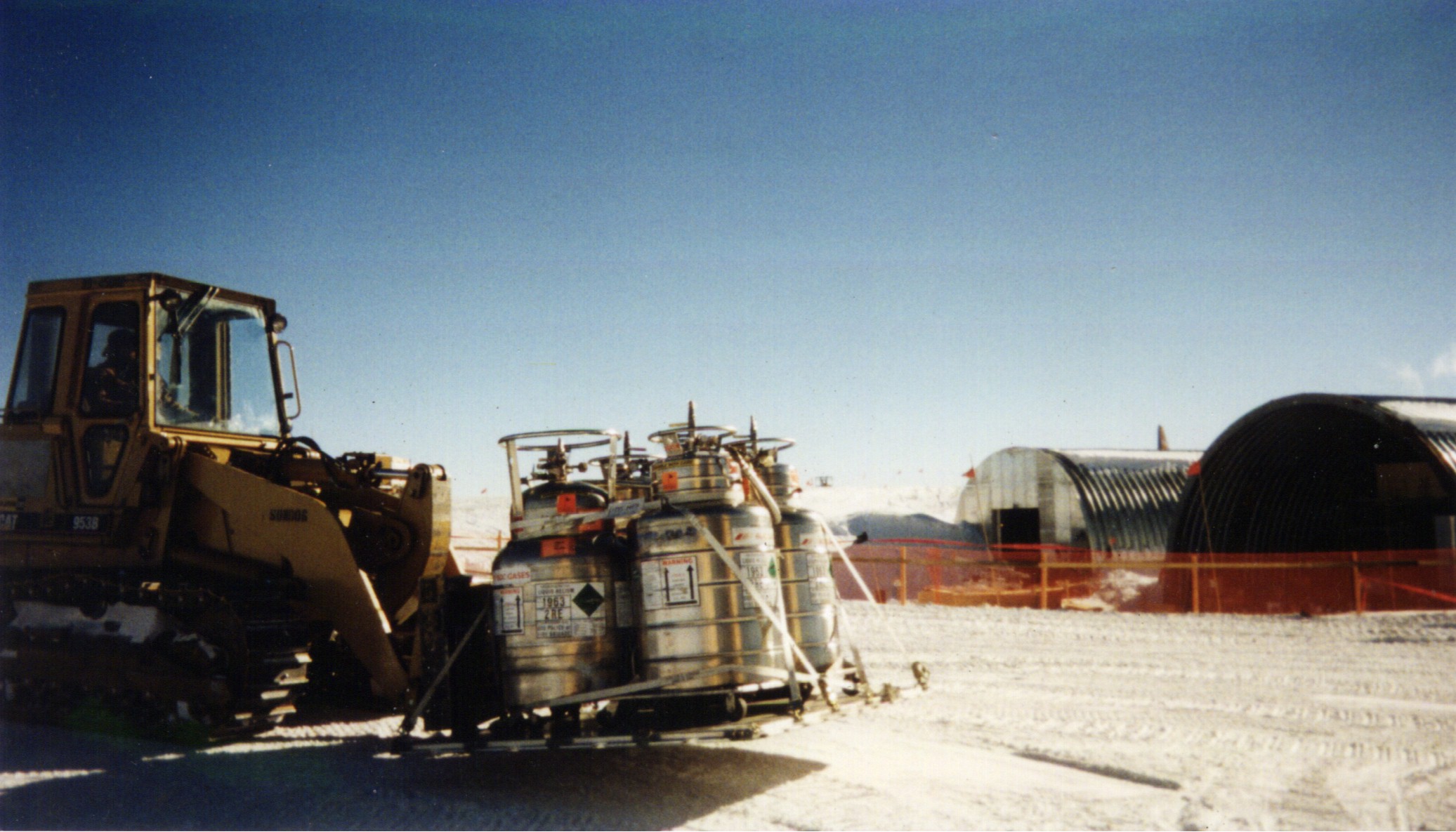
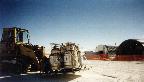 small image & large image--Helium is delivered for SPARO at South Pole. small image & large image--Helium is delivered for SPARO at South Pole.
|
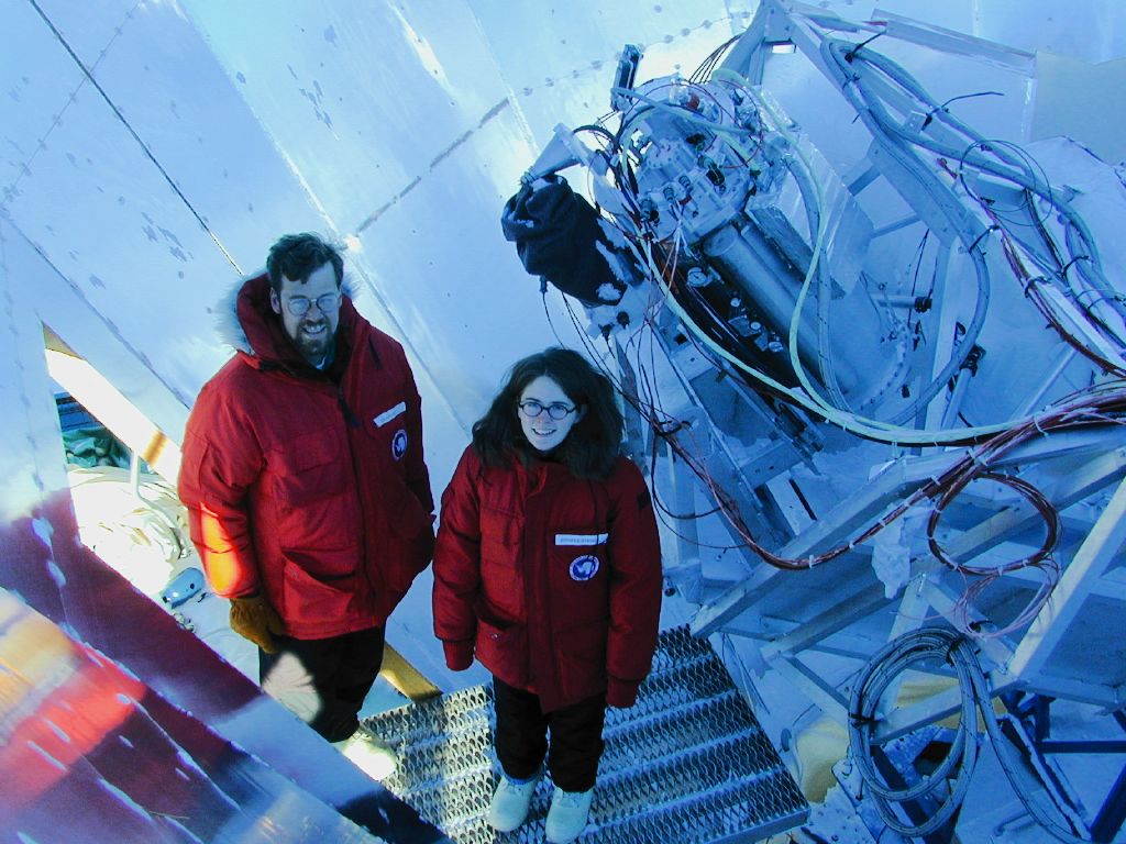 SPARO installed on Viper (February 2000), pictured with Giles Novak and Jen Marshall.